Wieland safeRELAY SNO 1012 Safety Relay 24V ac/dc, Single Channel 2 Safety Contacts

Documentos Técnicos
Especificações
Brand
WielandSupply Voltage
24V ac/dc
Number of Channels
1
Safety Contacts
2
Function
Safety Monitoring
Reset Method
Manual
Range
safeRELAY
Safety Category ISO 13849-1
2
PL ISO 13849-1
d
SIL IEC 61508
2
Terminal Type
Screw
Series
SNO 1012
Width
22.5mm
Depth
91.5mm
Performance Level
d
Length
96.5mm
País de Origem
Germany
Detalhes do produto
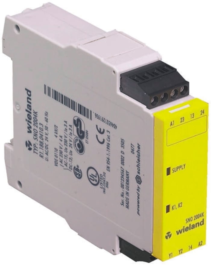
Wieland SNO 1012K Safety Relay
SNO 1012K Safety Relay Function - after the operating voltage (L+/L1) is applied via an unactuated emergency stop button or safety gate contact on A1 and A2, the device can be switched on via a Y1/Y2-connected reset button. When the device is on, the internal relays K1 and K2 are energized and the enabling current paths 13/14 and 23/24 are closed. When the emergency stop button or the safety gate contact is actuated, the current supply of the internal relays is interrupted and the enabling current paths are opened.

R$ 4.412,60
R$ 4.412,60 Each (Sem VAT)
1
R$ 4.412,60
R$ 4.412,60 Each (Sem VAT)
Informações de estoque temporariamente indisponíveis.
1
Informações de estoque temporariamente indisponíveis.
Documentos Técnicos
Especificações
Brand
WielandSupply Voltage
24V ac/dc
Number of Channels
1
Safety Contacts
2
Function
Safety Monitoring
Reset Method
Manual
Range
safeRELAY
Safety Category ISO 13849-1
2
PL ISO 13849-1
d
SIL IEC 61508
2
Terminal Type
Screw
Series
SNO 1012
Width
22.5mm
Depth
91.5mm
Performance Level
d
Length
96.5mm
País de Origem
Germany
Detalhes do produto
Wieland SNO 1012K Safety Relay
SNO 1012K Safety Relay Function - after the operating voltage (L+/L1) is applied via an unactuated emergency stop button or safety gate contact on A1 and A2, the device can be switched on via a Y1/Y2-connected reset button. When the device is on, the internal relays K1 and K2 are energized and the enabling current paths 13/14 and 23/24 are closed. When the emergency stop button or the safety gate contact is actuated, the current supply of the internal relays is interrupted and the enabling current paths are opened.